


As a premier supplier of human-machine interface (HMI) solutions, our engineers work with and design several types of membrane switches. From tactile and non-tactile response switches to the emerging technology of capacitive touch switches, we have provided proven quality for our customers depending on their needs.
With the increasing popularity of capacitive touch technology, one would believe that the tactile membrane switch concept would become obsolete. However, many HMI devices still utilize this technology because the capacitive touch technology can be environmentally sensitive. In addition, some users prefer the physical confirmation that a tactile switch provides when a button is pressed. These limitations, along with response speed, the need for an electrical charge to transfer from the user’s body to the switch (no gloves can be worn), and price have allowed the tactile membrane switch to remain a staple for HMI solutions.
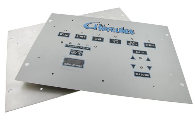
But have you ever explored what these types of membrane switches are made of and what each layer below the surface does? Most people look at a panel like the one below and have no idea that there are multiple layers at work. Here, we will explore their uses.

Graphic Overlay
The graphic overlay is the first layer and establishes the design and feel of a tactile membrane switch. It usually includes graphics and colors so that users can distinguish between the commands of each button; the typical user will not see or notice any of the layers behind. Graphic overlays can be made from a variety of materials; however, common materials include polyester and polycarbonate due to their improved readability, flexibility, vivid coloring options, and chemical resistance.
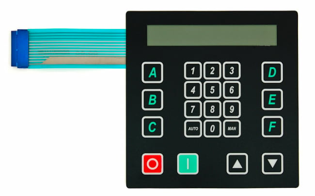
Example of a membrane switch with a graphic overlay.
Overlay Adhesive
Behind the overlay will be a very thin layer of adhesive, which binds the overlay to the next layer behind it. A common material for the adhesive is acrylic, which can come in several different thicknesses, ranging from 1-17 millimeters.
Static Shielding
In some cases, the electronics inside the HMI unit are very sensitive to electrical currents, and any built up static charges that occur naturally in our bodies can damage these components once a person comes in contact with the membrane switch. To protect against this discharge, an electrostatic discharge (ESD) layer can be added to the assembly. The shielding layer does not eliminate static. It simply routes a conductive trace to a safe grounded contact to eliminate damage and is typically made from a thin layer of aluminum foil.
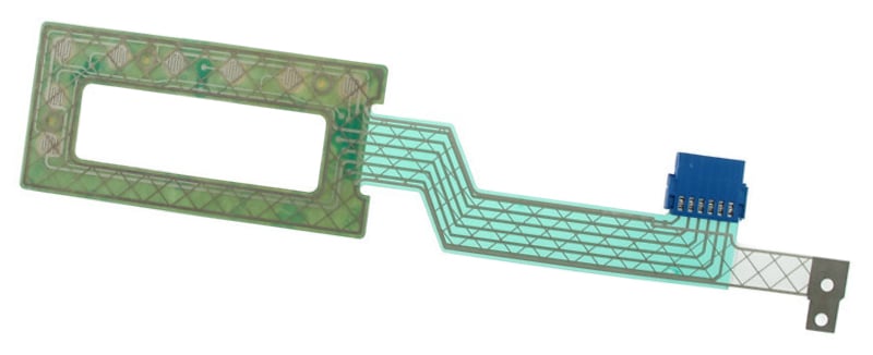
Example of a membrane switch with shielding layer.
Dome Array and Dome Spacer
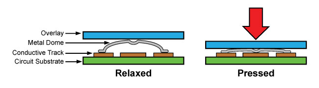
A tactile switch provides tangible feedback to the user when a symbol on the overlay is pressed down. Some describe this feedback as a snap. A metal dome is placed under the overlay and once pressed provides momentary contact with the circuit layer. The metal domes are supported by an adhesive spacer layer, and in their relaxed state, the legs of the dome rest on the outer edge of the primary pathway. When pressed, the dome collapses and makes contact with the secondary pathway in the center, thereby completing the circuit. This is demonstrated clearly in the diagram below:
Circuitry
The pathways the domes sit on belong to the circuit layer of the membrane switch. When a button on the overlay is pressed, the dome contacts the pathway made of either conductive ink or traces on a printed circuit board, which close the electrical switch and perform the command. This circuitry layer can either be a flexible printed circuit, or a rigid printed circuit depending on the application.
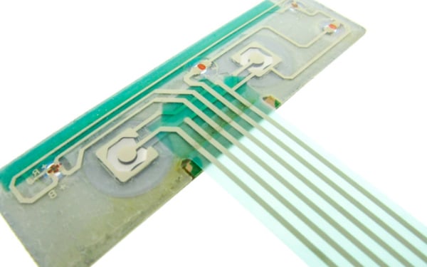
Example of circuit layer of the membrane switch.
Rear Adhesive
The rear adhesive layer bonds the entire membrane switch package to the product enclosure, housing, or to a rigid support panel. The material for this layer is often an acrylic adhesive just like the overlay adhesive.
Rigid Support Layer
Most often, the HMI products that are manufactured are often just one part of a larger assembly for our customers. As such, many of our membrane switch assemblies include a rigid support layer, or backplate, as the final layer. This is usually a metal frame that attaches to the rest of the assembly with the rear adhesive. Common materials can be aluminum, FR-4, steel, etc. The backplate often includes hardware such as studs or standoffs that allow for the membrane switch to be mounted to other components.
Example of membrane switch assemblies with rigid support layer.
Summary
There is much more to a membrane switch than meets the eye. Although the user only comes into contact with the overlay and buttons being pushed, there are many components at work providing the experience and allowing the user to perform their desired commands.
Key Takeaways
- Tactile isn’t dead: Despite capacitive popularity, tactile membrane switches persist due to physical feedback, lower cost, glove use, and better tolerance to environmental noise.
- Layered stack-up: A membrane switch is a multi-layer assembly: graphic overlay → overlay adhesive → (optional) ESD/static shield → dome array + spacer (for the “snap”) → circuitry (flex or rigid) → rear adhesive → rigid support/backplate.
- Graphic overlay drives UX: Polyester/polycarbonate overlays provide durability, chemical resistance, and clear legends, what the user sees and feels.
- Tactile feedback mechanics: Metal domes sit over traces; pressing collapses the dome through a spacer window to short primary/secondary paths, closing the circuit and delivering a crisp “click.”
- Integration & protection: Optional ESD layers shunt static to ground; rear adhesive bonds to the enclosure; backplates (aluminum, FR-4, steel) add rigidity and mounting features (studs/standoffs).


