


All customers have questions when it comes to PCB laminate materials, so we took some of the most common questions and put together a helpful FAQ to bring you answers and solutions faster.
When calling out an FR4 type from the IPC spec, which are Most common and what characteristics do they have?
For FR4, these fall into two major categories, which are effectively low temperature and high temperature. The low temperature stuff is perfectly suitable for the old tin, lead, hot air solder level type assemblies, i.e. the ones that bond with their board when you receive them.

The higher temp is for lead-free and RoHS-compliant type work because it sees higher soldering temperatures and oftentimes multiple thermal cycles, so it must be more robust. Basically, if you need a low-temp material, you want to call out the 4101/21 material. That has a glass transition temperature of only 115°, but almost all the products that are sold are capable of reaching at least 130° and some go as high as 140°. It is a pretty good choice if you're doing a hot air solder level type board.
If you're doing a higher temperature circuit board, I always recommend that you go straight to the /126. That's 170° glass transition. It uses RoHS-compliant bromine flame retardant and inorganic fillers, which are stable and best suited for the high temperature applications.
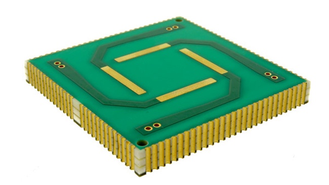
Printed Circuit Board Manufactured with High-Temp Material
What we would recommend is using /21 for low temp, /126 for high temp.
If your high frequency materials are not in stock, how long Will They take?
This is a good question that comes up all the time.
Usually, it can vary from just a couple of days to as many as 10 days. And it really depends on a lot of different factors. First, it depends on how exotic the laminate material is. If it's something where they don't keep a lot in a warehouse, you could be waiting for the material manufacturer to actually perform a build.
They do periodic builds every two weeks or however often, potentially waiting until they have a demand built up for it. Other times, if it's like 4350 or 3003 or something similar, it's probably available from a distributor. It could be a local distributor, or somebody in the country at least, in which case it's usually going to be a matter of just a few days. But as always, it always pays off in cases when you're building something nonstandard to try to get it on order as quickly as possible in order to get your supplier on the material ordering as quickly as possible.
Is it possible to V-score high frequency materials?
I've been told that's not a good idea. I would say that whoever said that was generally right. There are a few problems with this. One is that some of the high frequency laminate materials are very soft and kind of fibrous, and therefore don't take well to being V-scored because a V-score (also known as v score or v cut) is basically two circular saws facing each other, and anything fibrous like that will likely get torn up.
It is also not going to snap very well because some of these materials are very pliable. They're almost like the lead sheet that you might use to flash a chimney on the roof of a house. They kind of have that feeling, some of them. Others are much more rigid.
In general, V-scoring these types of laminate materials is not a great idea.
The other thing is that there's usually copper all the way to the edges on these types of PCB designs. Again, if you're V-scoring through copper, it's going to lift it all up. It's going to look like the edge of a can that you just ran through a can opener. It's going to be a lot of lifted copper and is going to have sharp edges. It could even pull away from the surface at some places and peel a large strip away from the surface.
Some of these circuit boards are built very thin. With V-scoring being two circular saw blades pointed towards each other, there's a minimum distance you must observe between those two blades before they're hitting each other, so you need to consider that.
If you have a thin material, you can't even really make a meaningful cut into the board without violating that minimum distance. So, I would say you typically don't want to V-score these types of circuit boards, which is a shame because V-scoring improves your material utilization, but unfortunately, it's not usually a great solution.
PCB Manufacturing Explained: The V-Score & Jump Scoring Process
Regarding basic stack-ups, are you able to do higher layer count multi-layers using just high frequency materials?
The answer to that is yes. From a very simple three-layer to a hybrid PCB design with more layers that is mixed with FR4. All high frequency stack-ups are possible when they're necessary. Whether it's necessary or not to build them all out of high frequency is, of course, up to you and what your signal integrity needs are, but it is doable.
Material data sheets show different dielectric constants in the same board. How is that possible?
When reviewing just a small section of the data sheet, understand that they are applicable to not just a small section, but to the whole series of materials. For example, when we look at Rogers 3003, we must consider that the Rogers 3000 series is comprised of four different materials: 3003, 3006, 3010, and 3035. While they all have very similar mechanical properties, there can be some key differences.
These materials can be combined into the same stack-up, but they all have different dielectric constants, which makes them useful. If you have something where you have differences in your signal integrity requirements, your signal speeds, and so forth, you can mix and match these in the same stack-up and they'll behave the same way. They will drill and process the same way, but electrically, they will each be unique and different. Just going through what those dielectric constant differences are, they can be wildly different in some cases. For example, 3003 runs at 3.0, 3006 at 3.5, 3010 at 6.5 and the 3035 is 11.2, almost unheard of as a dielectric constant.
For PCB designers who are accustomed to dealing primarily with FR4, that's quite a large number, hence where the confusion sets in. The explanation is because it’s composed of four different materials, which makes it possible to have different dielectric constants within the same stack-up for the same board.

Summary
This FAQ covers common questions about PCB laminate materials, focusing on FR4 and high-frequency options. Designers should select FR4/21 for low-temperature applications and FR4/126 for high-temperature, RoHS-compliant boards. Material availability for high-frequency laminates varies based on how specialized the product is, often taking several days to source. V-scoring high-frequency materials are generally not advised due to their softness, copper exposure, and thinness.
Multi-layer stack-ups using only high-frequency materials are possible, but often hybrid designs with FR4 are more practical. Differences in dielectric constants across a single data sheet result from multiple related materials in the same series, which can be combined for tailored electrical performance.
Key Takeaways
- FR4 Selection: Use FR4/21 for low-temperature, tin-lead solder applications and FR4/126 for high-temperature, RoHS-compliant builds requiring higher glass transition temperatures.
- Material Availability: Lead times for high-frequency laminates range from a few days to two weeks, depending on how exotic the material is and distributor stock levels.
- Avoid V-Scoring High-Frequency Boards: These materials are often soft, fibrous, or copper-heavy, making them prone to tearing and edge defects when scored.
- Layer Stack-Up Flexibility: Full high-frequency or hybrid FR4 stack-ups are possible depending on signal integrity needs and design complexity.
- Dielectric Constant Variation: Differences within a material series (e.g., Rogers 3000 series) explain variations in dielectric constants, enabling designers to fine-tune performance within a single stack-up.


