


You may have encountered the acronym STP or STEP while learning about or working on projects that involve computer-aided design. But what exactly is it? A STEP file is a 3D-model file formatted in STEP, which stands for Standard for the Exchange of Product Data. STEP files are used to store 3D-image data in an ASCII format, following the standards defined in ISO 10303-21, introduced by the ISO committee in 1994. This specification created a file structure which could be recognized by multiple modeling programs, thus enhancing the ability for design data to be exchanged.
Since its inception, the STEP file has become the most popular exchange format, as users do not need to use the same modeling program to work together. For example, when a company sends a 3D model to a manufacturer for them to produce a part, both companies may use different software programs but can work together exchanging instructions and ideas and can pass models back and forth for evaluation.

History of the STEP File
Before the onset of the STEP file, Initial Graphics Exchange Specification (IGES) files were the most popular format used to share data. IGES was designed as a neutral format for the exchange of CAD models and was first published in January 1980 by the U.S. National Bureau of Standards.
While it is still used in a variety of manufacturing industries, after the initial release of STEP in 1994, interest in further development of IGES declined, and Version 5.3 was the last published standard in 1996. So, while there is nothing wrong with using IGES files in CAD, STEP files tend to be solid models, whereas IGES files are more often surface models, which could have gaps and missing faces.
The IGES format has not been updated in more than 20 years. STEP is a newer technology with more than 20 years of global use and continual development.
STEP File Types
From the image below you can see that there are numerous types of files that a 3D model can be saved as. STEP allows users to save files in two format types: AP203 and AP214.
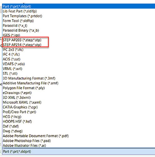
Example of STEP AP203 and AP214 file types.
The Application Protocols (APs) essentially define what type of data the file will contain. A STEP AP203 file defines the geometry, topology, and configuration management data of solid models for mechanical parts and assemblies. STEP AP214 files define everything a STEP AP203 file does with the addition of colors, layers, geometric dimensioning and tolerance, and design intent. It is important that the user of the CAD system chooses the correct type of AP file based on which details of the model are most important, otherwise the file may not export the data required.
STEP File Capabilities
Another important item to note, when sharing or importing assemblies into your CAD program, a STEP assembly cannot be broken into individual parts like the original file can be. Speaking specifically from my experience with SolidWorks, individual parts of a STEP assembly show up as solid bodies in the assembly but cannot be moved or edited. The STEP assembly is imported as a single model. This can be both a good thing if you are sending out a model and do not want to give the other person access to the individual assembly parts. However, this can cause issues when trying to analyze an assembly that you receive in STEP format.
Luckily, there is a way to work around this. Simply open the System Options by pressing the gear symbol at the top of your screen. Then press the Import tab.
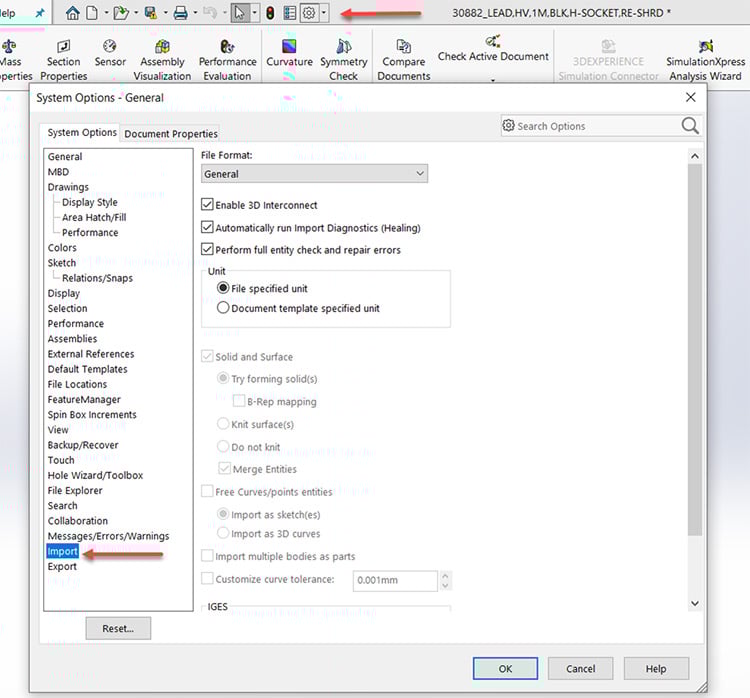
Example of STEP file format capabilities in SolidWorks.
After this, click the File Format drop down menu and select STEP/IGES/ACIS.
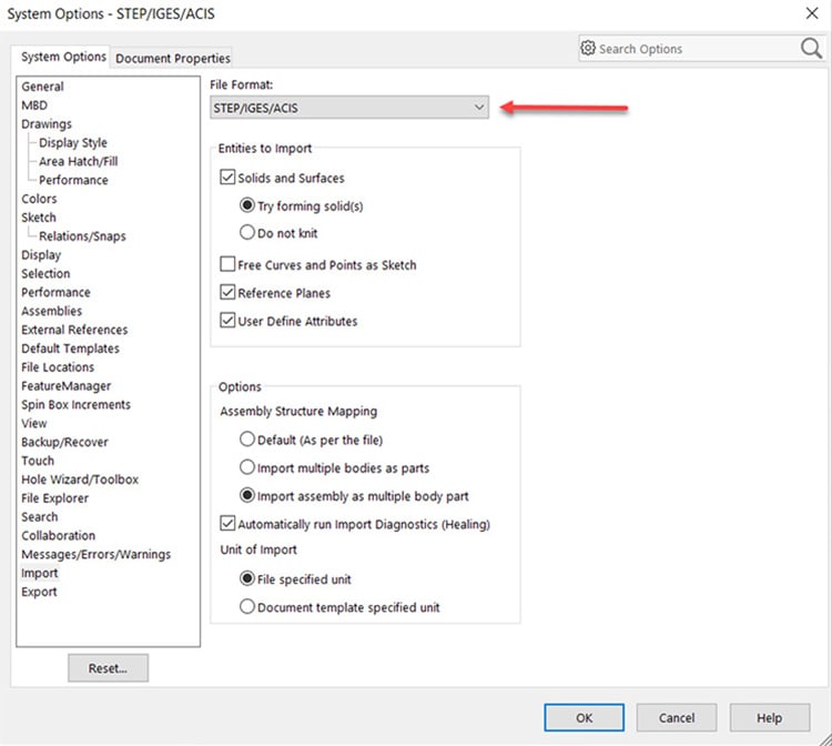
Example of STEP file format options in SolidWorks.
Here, you will find the options under Assembly Structure Mapping. Select Import assembly as multiple body part and click OK.
The individual parts that make up the assembly model will be editable as if you had built the model yourself, and this can be very helpful when trying to analyze the model and understand the design intent.
Summary
The STEP file changed the landscape for data transfer in the world of computer aided design. It remains the most common format used for sharing 3D CAD data. It is superior to the IGES file in a number of ways and has allowed users of different CAD systems to share data and more importantly, ideas.
Here at Epec, our engineering team has become very experienced with using STEP files over the years. It is a common practice for us to send and receive these files during the development stages of a project. Thanks to the STEP file, our engineering team is able work with customers who use different CAD software and do not miss a beat. Our business is dependent on our ability to analyze and understand the design with the intent our customers seek to produce. The standard created by the STEP file helps us do so, and we continue to learn more about the capabilities of STEP with each new experience.
Key Takeaways
- STEP is the global standard for 3D model exchange: STEP (Standard for the Exchange of Product Data, ISO 10303-21) enables cross-platform CAD collaboration by storing 3D models in a universal ASCII format recognized by multiple programs.
- It replaced IGES as the industry standard: While IGES was once widely used, it is now outdated and limited to surface models. STEP offers more robust solid models and has been continuously updated for more than 20 years.
- Two STEP formats serve different needs: AP203 covers geometry, topology, and configuration management, while AP214 adds support for colors, layers, tolerances, and design intent. Choosing the correct format ensures that critical design data transfers properly.
- Assembly structure behavior matters: By default, STEP imports assemblies as single solid models, which can protect proprietary designs but limit editing. CAD tools like SolidWorks allow assemblies to be imported as multiple editable parts when needed.
- STEP supports seamless collaboration: Its universality makes it easier for companies, suppliers, and manufacturers to share designs, exchange ideas, and analyze intent without being restricted by software compatibility.


