


The smallest bend radius that can be used on a membrane switch tail will depend on the type of design. Deciding factors will depend on whether or not the user interface is constructed with one tail/circuit layer or dual tail/circuit layers, and where the bend is located.

A circuit is the functioning layer or sub-layer of a membrane switch. The bend radius shouldn't be close to the terminating connector. Other than the connector location, the bend radius on a single tail/circuit layer can be a 0.100 inch radius. However, if the bend is right at the tail exit location on the final assembly, the radius and resulting stress will be seen in the area within the graphic overlay.
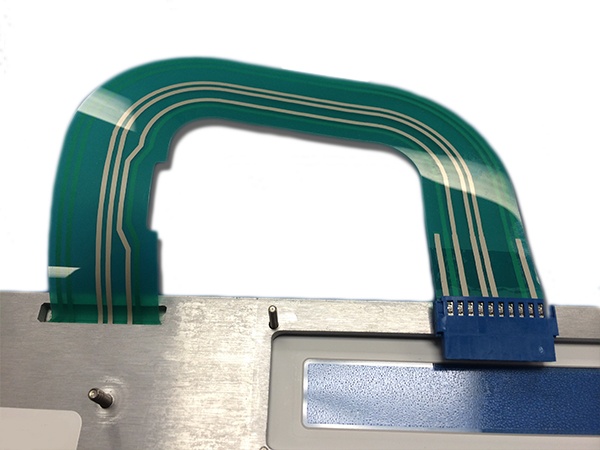
Membrane Switch Tail Illustrating Bend Radius
Membrane switches are connected by a flexible tail that is cut from the circuit material. Long-term stress on flexible silver printed circuitry will cause the pressure sensitive adhesive to creep and sheer and will eventually pull away. Flexible membranes switches, by their design and construction, like to stay flat and not be stressed by bending.
Some customer applications require that the tail of the membrane switch be bent at or close to the exit point(s). It's wise to use caution when conducting a bend of flexible circuits. If the bend isn't conducted correctly, the circuit trace could become damaged in close proximity of where the bend took place, increasing the chances of circuit failure.
Summary
When designing a custom user interface, it is important to know what the bend radius requirements are. If space is an issue in your application, it is always better to get your supplier's engineering team onboard to ensure your design will function properly once manufactured.
Key Takeaways
- Bend radius depends on design type: Single-tail/circuit layer designs can typically support a 0.100-inch radius, but dual-layer or complex layouts require more caution.
- Avoid bending near connectors: Stress close to the terminating connector or tail exit can transfer into the graphic overlay, risking long-term damage.
- Membrane switches prefer flat layouts: Flexible silver printed circuitry, and adhesives are not designed for repeated bending, and stress can cause delamination or adhesive creep.
- Improper bending increases failure risk: Bends too close to traces may cause cracks or breaks in the circuit, leading to higher chances of electrical failure.
- Engage engineering support early: When space constraints force tight bends, consulting your supplier’s engineering team ensures the design will perform reliably in production.


