




When developing a custom battery pack, engineering teams can spend months validating cell chemistry and fine-tuning the Battery Management System (BMS) architecture. Yet we often see the charging solution treated as an afterthought, selected later in the process solely based on the battery pack's voltage and current characteristics.
This is a missed opportunity. The charger isn't just a power supply; it's the external half of your battery's control system. Integrating charger design early helps ensure safety and reliability, making your team confident in the system's effectiveness.
Here's the 7-step protocol we use at Epec to design a battery charger and battery pack into a single, reliable system, highlighting its comprehensive approach to safety and reliability and giving your team confidence in the process.

1. Pre-Charge Qualification (The System Health Check)
A charging sequence should always begin before any bulk current flows. The charger first needs to "poll" the battery to read the open-circuit voltage.
This initial check verifies the integrity of the battery pack. If the voltage falls below a critical threshold (typically specified in the cell datasheet), it indicates the pack is deeply discharged or potentially compromised. Detecting this early reassures your team that safety is prioritized, preventing high-current charges into damaged circuits.
2. Low-Current Pre-Conditioning
If that pre-check shows a voltage between the critical threshold and the standard operating range (e.g., 2.5V to 3.0V), you shouldn't jump to full power. The protocol should initiate a preconditioning phase with a reduced current, typically around 0.1C, to gently raise the voltage, giving your team confidence in safeguarding battery longevity.
Charging a deeply discharged lithium-ion cell at full current immediately stresses the anode and the internal protection layers. At low voltages, the cell's internal structure is not stable enough to accept a high current. By charging at full current before the cell has reached a safe limit, you can experience elevated heat and potential permanent capacity loss. By charging slowly around 0.1C, it allows the cell to recover to a stable operating region and ensures the internal chemistry is behaving normally.
3. Soft-Start Ramp
Once the battery is healthy enough for full-current charging, the handoff needs to be smooth. Rather than switching to maximum current immediately, a soft-start algorithm ramps the current up over a few seconds.
In the past, quickly triggering a full-current event could trip some protection circuitry in the designed battery pack. Depending on the in-rush current, the BMS Over Current Protection can be triggered, disconnecting the battery's output and protecting the battery. To the end user, this looks like a dead battery. By implementing a slower ramp, we preserve any power FETs and protection circuitry from unnecessary stress.
4. Constant Current (CC) with Active Thermal Monitoring
Now, the battery is receiving its maximum rated current (C-Rate). Because this phase involves the highest energy transfer, it naturally generates heat. Effective thermal management here requires more than just a high-temperature cutoff; advanced chargers monitor the pack's NTC thermistor in real-time and follow JEITA guidelines.
- Standard Range (10°C to 45°C): Full charge current is applied.
- Marginal Range: In cooler (0-10°C) or warmer (45-50°C) conditions, the charger automatically throttles (derates) the current.
This prevents the accelerated degradation that happens when you push batteries hard in non-ideal thermal windows.
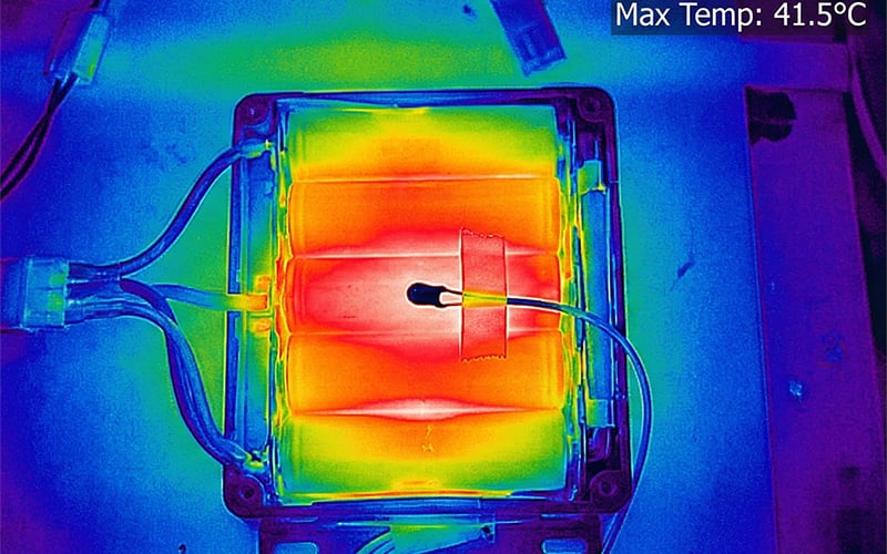
Thermal imaging of a battery pack’s heat buildup. Temperature monitoring helps inform charging decisions during the constant-current phase.
5. Constant Voltage (CV) Saturation
When charging lithium-ion batteries, it's crucial to understand that once the battery voltage hits about 4.2V per cell, the charger shifts from constant current to constant voltage. This transition is key for safe charging, as the current naturally decreases, preventing overcharging and potential damage.
During the constant-voltage phase, the charger maintains a steady output as the current declines. To enhance safety, it's best to set the charger's target voltage slightly below the Over-Voltage Protection (OVP) trip point of the Battery Management System. If the charger voltage is too close to the OVP limit, small fluctuations might cause the BMS to stop charging prematurely.
By setting a lower target voltage, the charger can effectively manage voltage without risking BMS interruptions, allowing the battery to reach its optimal charge while ensuring safety.
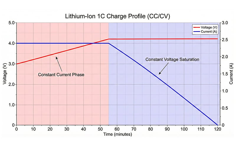
Illustrative lithium-ion charge profile: Current stays steady as voltage rises to 4.2V, then tapers as the charger holds at that voltage.
6. The Safety Timer
Current tapering usually signals the end of a charge, but relying on that alone is risky. If a parasitic load is active, such as a device updating its system while plugged in, the current may not drop below the termination threshold.
Without a secondary termination method, the charger will continue supplying energy indefinitely. This "endless charge" creates heat and stresses the electrolyte. A backup safety timer ensures that, regardless of load conditions, the charging cycle terminates after a set duration.
7. Proper Termination (The Hysteresis Loop)
Finally, once the charge is complete, it must stop. Unlike lead-acid applications, you shouldn't use "float charging" to maintain voltage. Holding a lithium cell at 100% SoC places the chemistry in its most unstable state, accelerating electrolyte oxidation.
Instead, use a hysteresis strategy: The charger terminates the cycle and enters standby. It only re-initiates a "top-off" charge once the voltage drops by a specific percentage. This reduces time-at-max-voltage and significantly extends the battery's operational life.
Integrating the Design
The most reliable power systems combine the battery and the charger. By including charger selection in the initial battery design phase, you can establish key protocols early. This approach leads to a safer product with fewer field failures and ensures that the external power supply is compatible with your battery pack's internal chemistry.
Summary
A reliable battery pack depends on how it is charged, not just how it is built. Epec’s seven-step protocol treats the charger and pack as one system: check pack health, recover low-voltage cells gently, ramp current smoothly, monitor temperature, control voltage, enforce a safety timer, and stop charging with a defined recharge threshold. Choosing the charger early helps the team align these behaviors with the cells and BMS, reducing avoidable stress and field failures.
Key Takeaways
- Check pack voltage before allowing significant charge current.
- Use reduced current to recover cells that are below their normal operating range, when the cell manufacturer permits recovery.
- Ramp charge current gradually to avoid unnecessary protection trips.
- Match current and voltage limits to cell temperature, chemistry, and BMS settings.
- End charging reliably, with a backup timer and a defined threshold for restarting the next charge cycle.