
In order for Epec or any PCB fabrication company to quote your circuit boards accurately and with minimum delays, it's important to supply a complete PCB data file set, using industry-standard file types. Before you look at getting your quote, learn what information you need to supply to ensure a smooth PCB fabrication process.
PCB Gerber Data Package
Gerber Extended (RS274X) are preferred. This should be set as your CAD system's default output file type. All other file types must eventually end up as RS274X for artwork plotting. Starting with RS274X eliminates interpretation errors.

Old-style Gerber files with separate aperture lists are acceptable only if that's all you have. They do however cause delays in loading. Errors in aperture entry can even cause your design to be corrupted potentially, causing your entire order to be scrapped.
ODB++ is acceptable. It should always be supplied in a single compressed file, typically with a .TGZ extension. DXF files are acceptable, but take note that the process of converting them to Gerber format for photo plotting is potentially error-prone. We always supply check plots for your review and approval before use. Given the fact that DXF files are not production-ready, they are subject to a one-time data preparation charge. They are also not suitable for quick turnaround orders. Add 1 week for data preparation in addition to production time.In some cases, Epec can work with other file formats not listed above. Before placing an order, call us to tell us what you have. We will review to see if we can work with it.
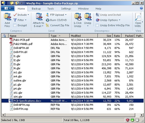
Example of PCB Fabrication Data Package
Necessary Files to Manufacture Your PCB
Below is a list of all the necessary files that should be included to fabricate a printed circuit board.
- All copper layers
- All solder mask, silkscreen, and paste layers
- An accurate outline, with cutouts, slots, etc. represented if possible
- One Excellon format ASCII drill file for each drill cycle (through, blind or buried, slotted, etc.) The drill file should include tool codes with diameter information.
- One or more fabrication drawings or similar documents
Information to Include in Your Circuit Board Fabrication Instructions
- Hole sizes with tolerances, plus plating status information (PTH / NPTH)
- Board outline dimensions, including tolerances
- Hole or other mechanical feature to edge dimensions
- Finished copper weights of both internal and external layers
- Finished PCB thickness with tolerances, and measurement criteria
- Surface finish preference
- Solder mask requirements
- Silkscreen requirements
- Any additional requirements (impedance control, specific dielectric thicknesses, via plugging, etc.)
- Technical contact information
- For PCBs delivered in panel form for assembly, describe or draw the required layout.
Acceptable PCB Fabrication Drawing file formats
- RS274X Gerber (.gbr, .pho, etc.)
- Adobe Acrobat (.pdf)
- AutoCAD (.dwg or .dxf)
- HPGL (.hpg, .plt)
- Graphic file (.jpg, .gif, .tif, etc.)
- ODB++ (.tgz)
- Readme files (.doc, .txt, .rpt)
For more information check out our section on PCB design and layout or download our free circuit board design guide.


